Displacement
measurement using LDR
Setup:
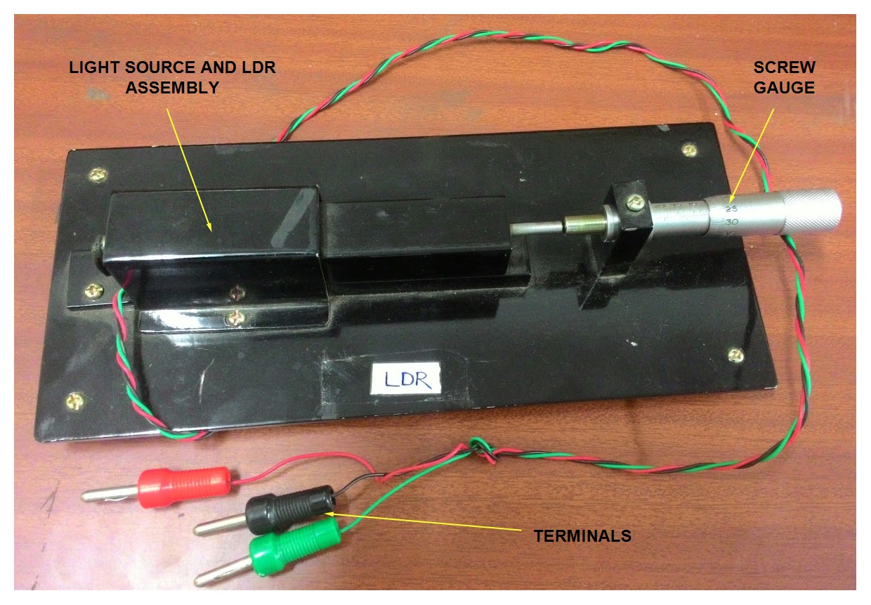
The complete setup consists of a sensor module and its signal
conditioning circuit. In the sensor module there is an LDR and a light source
enclosed inside a metallic enclosure. There is a 20 mm screw gauge to provide
known displacement. A rod is connected to the LDR inside the enclosure and it
is attached to the screw gauge outside. Hence we can provide known displacement
to the LDR by the screw gauge. Three terminals are attached to the sensor module,
Vcc and GND for the light source and one terminal of LDR w.r.t ground. The output
of the sensor module is fed to the signal conditioning and processing unit. There
is a IC regulated power supply source that provides constant voltage to all the
circuits for their functioning. A zero adjustment and gain adjustment pot is
there for calibration purpose. And there is a four 7 segment LED display which
shows the output directly in mm.
Working:
LDR stands for Light Dependent Resistor, it is basically a resistor
whose resistance depends upon light intensity. And the relation is inversely proportional
means when the light intensity is more the resistance is less and vice versa. The
LDR is attached to the rod at one end inside the enclosure. The light source
has been kept fix. When the screw gauge is rotated it gives a linear
displacement to the rod attached to it. This displacement changes the distance
between light source and LDR. When the distance is less the resistance of LDR
is less and when the distance is more the resistance will be more. This change
of resistance is given to the signal conditioning circuit where it is
calibrated to give the output directly in mm.

Procedure:
Connect the LDR sensor leads with the trainer kit terminals according
to their colors. Switch ON the power. Keep the DPM switch at mm position. Connect
a patch cord between output terminal and DPM terminal. Keep the micrometer at
zero position and adjust zero pot to set zero reading on the display, set the
micrometer at 15mm and adjust the adder pot to show 15mm on the display. Now increase
the micrometer in steps of 1 mm and note down the in following table in
increasing and decreasing mode. Plot the graph between micrometer reading and
DPM reading in mm.
Observation:
Sl no
|
Reading in
increasing mode
|
Reading in decreasing mode
|
||
Micrometer
reading (mm)
|
DPM
reading (mm)
|
Micrometer
reading (mm)
|
DPM
reading (mm)
|
|
Displacement measurement using linear pot
Setup:
The setup has a linear pot and a screw gauge arrangement module and
its signal conditioning circuit. The linear pot is a sliding type potentiometer
enclosed inside a metallic enclosure. A rod is attached to the sliding arm of
the potentiometer at one end and to the screw gauge at the other end. Three terminals
are taken out from the sensor (pot), one for Vcc one for GND and another for
output from the wiper of the pot. These three terminals are connected to the
signal conditioning where the output is processed and calibrated in terms of
displacement. In the signal conditioning unit there is an IC regulated power
supply source that provides constant voltage to all the circuitry inside the
unit and to the pot also. There is a zero and span adjustment pot for
calibration. And a four 7 segment LED display screen.

Working:
The pot is generally a variable resistor. It has three pin/ terminal,
two are fixed and one is sliding. Between two end terminals the resistance is
fixed/constant, and between the sliding terminal and the fixed terminal the
resistance is variable according to the position of the sliding arm. The resistance
between the sliding arm and any one of the fixed terminal is depends upon the
physical distance between them. If the distance is more the resistance will
more and vice versa. If a constant voltage is applied between the two fixed terminals
the pot creates a voltage divider circuit itself. The output voltage between
sliding terminal w.r.t GND depends upon the resistance which eventually depends
upon the position of the slider. The rod connected between the slider and the
screw gauge provides the known displacement to the slider of the pot. The output
voltage is further processed and calibrated in terms of displacement.

Procedure:
Connect the linear potentiometer leads with the trainer kit terminals according
to their colors. Keep the DPM switch at mm position. Connect patch cord between
output terminal and DPM terminal. Switch ON the trainer kit. Keep the
micrometer at zero position and adjust zero pot to set zero reading on the
display, set the micrometer at 20mm and adjust the adder pot to show 20mm on
the display. Now increase the micrometer in steps of 1 mm and note down the in
following table in increasing and decreasing mode. Plot the graph between
micrometer reading and DPM reading in mm.
Observation:
Sl no
|
Reading in
increasing mode
|
Reading in decreasing mode
|
||
Micrometer
reading (mm)
|
DPM
reading (mm)
|
Micrometer
reading (mm)
|
DPM
reading (mm)
|
|
Displacement measurement using strain gauge transducer:
Setup:
In the setup the transducer used for displacement measurement is
strain gauge. The transducer module consists of four strain gauges with some
mechanical arrangement to measure linear displacement provided by a screw
gauge. In the mechanical arrangement a steel plate (measuring scale) is used,
four strain gauges are fixed over it, two on each side. One end of the scale is
fixed, but the other is exposed to linear force. A conical shaped plastic
object having 3cm length and 1.5cm dia is fixed at one end of the rod, and the
other end of the rod is attached with the screw gauge. The four strain gauges
form a Wheatstone bridge so four leads are taken out of the transducer for
electrical connection. These four leads are connected to the signal
conditioning unit. In the signal conditioning unit there is an excitation
source, some electronics circuitry, a zero adjustment and span adjustment pot
for calibration and a four 7 segment display unit.

Working:
The linear displacement provided by the screw gauge is converted in to
the linear force by the conical plastic object, which is then converted in to
change in resistance of the strain gauge by the steel plate. This resistance
change causes voltage change in Wheatstone bridge output which is further
processed and calibrated in terms of linear displacement. And is directly shown
in the display unit in mm.

Procedure:
Connect the transducer leads with the trainer kit terminals. Keep DPM
switch at mm position. Connect patch cord between output terminal and DPM
terminal. Switch ON the unit. Keep the micrometer at zero position and adjust
zero pot to set zero reading on the display, set the micrometer at 20mm and
adjust the adder pot to show 20mm on the display. Now increase the micrometer
in steps of 1 mm and note down the in following table in increasing and
decreasing mode. Plot the graph between micrometer reading and DPM reading in
mm.
Observation:
Sl no
|
Reading in
increasing mode
|
Reading in decreasing mode
|
||
Micrometer
reading (mm)
|
DPM
reading (mm)
|
Micrometer
reading (mm)
|
DPM
reading (mm)
|
|
The procedure isn't full maybe you can try add more strain gauge theory and think about this
ReplyDelete