Objective:- Study of the diode as a clipper & clamper. Draw and measure the input and output waveform.
Required
Components: - Resistor 1K -1 No, Diode (1N4007 ) -1No, A.C Voltage, DC
Voltage, DSO, Coupling wires, Multi meter
Theory:-
For a clipping circuit at least two
components—an ideal diode and resistor are required and sometimes a dc battery
is also employed for fixing the clipping level. The diode acts as a closed
switch when forward biased and an open switch when reverse biased. Depending on
the orientation of the diode, the positive or negative region of the input
signal is “clipped” off and accordingly the diode clippers may be positive or
negative clippers. Half wave rectifier circuits can also be called the basic
clippers.
Biased Clipper – The level to which an
ac voltage is limited can be adjusted by adding a bias voltage v2, in series
with the diode. Biased clippers are
employed for this purpose. The circuit diagram for a biased positive clipper
(that is for removing a small portion of positive half cycle) is illustrated in figure.When the
input signal voltage is positive but does not exceed DC voltage V2, the diode
D remains reverse biased and most of the input voltage appears across the
output. When during the positive half cycle of input signal, the signal voltage
exceeds the DC voltage V2, the diode D is forward biased,i.e conducts heavily.
Procedure: - 1) Connect
the components according to the circuit diagram
given. Take VIN=5V rms , VBIAS=2.5v 2) Connect DSO across the load R and input
source. 3) Simultaneously measure both the input and output waveform in DSO
ch-1 and ch-2 respectively.
Positive
Bias Diode Clipping
Likewise, by reversing the diode and
the battery bias voltage, when a diode conducts the negative half cycle of the
output waveform is held to a level –VBIAS – 0.7V as shown.
Negative
Bias Diode Clipping
A variable diode clipping or diode
limiting level can be achieved by varying the bias voltage of the diodes. If
both the positive and the negative half cycles are to be clipped, then two
biased clipping diodes are used. But for both positive and negative diode
clipping, the bias voltage need not be the same. The positive bias voltage
could be at one level, for example 4 volts, and the negative bias voltage at
another, for example 6 volts as shown.
Diode
Clipping at Different Bias levels *take Vin = 7v Rms *
When the voltage of the positive
half cycle reaches +4.7 V, diode D1 conducts and limits the waveform
at +4.7 V. Diode D2 does not conduct until the voltage reaches –6.7
V. Therefore, all positive voltages above +4.7 V and negative voltages below
–6.7 V are automatically clipped.
The advantage of biased diode
clipping circuits is that it prevents the output signal from exceeding preset
voltage limits for both half cycles of the input waveform, which could be an
input from a noisy sensor or the positive and negative supply rails of a power
supply.
If the diode clipping levels are set
too low or the input waveform is too great then the elimination of both
waveform peaks could end up with a square-wave shaped waveform.
Object :- Study of diode as a positive clamper
Required Components: -Capacitor-1uF 1No, Resistor-680K-1
No, Diode ( IN4007 )-1No, A.C Voltage Source, DC Voltage, DSO
Theory: -A Clamper Circuit is a circuit that adds a DC level to an AC signal.A Clamper circuit can be defined as the circuit that consists of a
diode, a resistor and a capacitor that shifts the waveform to a desired
DC level without changing the actual appearance of the applied signal. The different types of clampers are positive and negative clampers.
The magnitude of R and C must be
chosen such that the time constant RC is large enough to ensure that the
voltage across the capacitor does not discharge significantly during the
interval the diode is non- conducting.
A Clamping circuit restores the DC level. When a negative peak of the
signal is raised above to the zero level, then the signal is said to be
positively clamped.
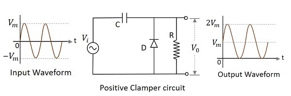
A Positive Clamper circuit is one that consists of a diode, a
resistor and a capacitor and that shifts the output signal to the
positive portion of the input signal. The figure below explains the
construction of a positive clamper circuit.
Initially when the input is given, the capacitor is not yet charged
and the diode is reverse biased. The output is not considered at this
point of time. During the negative half cycle, at the peak value, the
capacitor gets charged with negative on one plate and positive on the
other. The capacitor is now charged to its peak value Vm
. The diode is forward biased and conducts heavily.
During the next positive half cycle, the capacitor is charged to
positive Vm while the diode gets reverse biased and gets open circuited.
The output of the circuit at this moment will be
V0=Vi+Vm
Hence the signal is positively clamped as shown in the above figure.
The output signal changes according to the changes in the input, but
shifts the level according to the charge on the capacitor, as it adds
the input voltage.
Positive Clamper
The circuit for a positive clamper
is shown in the figure. During the negative half cycle of the input signal, the
diode conducts and acts like a short circuit. The output voltage V0 =0V.The capacitor is charged to
the peak value of input voltage Vm. and it behaves like a
battery. During the positive half of the input signal, the diode does not
conduct and
acts
as an open circuit. Hence the output voltage V0 =Vm+Vm. This gives a positively
clamped voltage.
To see the output in DSO keep it in DC coupling mode.


I have enjoyed some of your posts and would like it if you would contact me.
ReplyDeleteGreat. Lets check out The Archers 2 Mod Apk for Android free
ReplyDeleteI have never seen such a great site that have the great work
ReplyDeleteOne of my favorite site on which i can get my favorite effcectum mod
ReplyDeleteNice and well defined article, Atal Tinkering Lab
ReplyDeleteNice Informative Article Can You Please Make More On the same.
ReplyDeleteHere are the Keywords you can Take as a Reference.
1 Sq mm wire
1.5 mm wire
4 Sq mm wire
Useful information. Thank you so much for sharing this article. Get to know about Bitwissend, website design company kottayam.
ReplyDeleteThe role of the diode in the clipping circuit is crucial as it switches between open and closed states depending on the input signal's polarity, enabling the circuit to clip the signal at specific levels. For more on industrial dust cleaners, visit
ReplyDeleteDust Cleaner
Pollution Control Equipments.
Depending on the diode's orientation, the clipping circuit can either be a positive or negative clipper. Positive clippers remove the positive half of the signal, while negative clippers remove the negative half, effectively controlling the waveform's limits. For centrifugal blowers
ReplyDeleteCentrifugal Blowers
Evaporative Aircooling System Manufacturer.