Instrumentation trainer:
The instrumentation trainer provided by Dynalog India contains
different sensors, electronics circuits and output display units. By using
these sensors and electronics circuits one can design an instrumentation
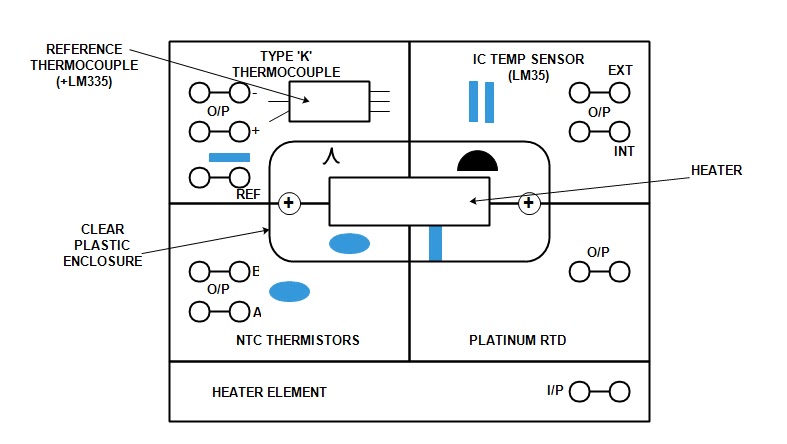
system. There is a temperature sensing unit which contains four temperature
sensors such as ‘K’ type thermocouple, LM35 IC temperature sensor, a Platinum
RTD and NTC thermistor. These transducers are mounted inside a clear plastic
enclosure which contains a heater. The heater used here is basically a 33Ω 5W
resistor. It generates heat when current is allowed to flow through it. Which
then raises the temperature inside the enclosure and that temperature is used
by the sensors for the experiments. In the case of NTC thermistors and
thermocouples, an additional separate unit is mounted outside the heated
enclosure. The externally mounted sensors are made available for comparison
between ambient temperature and the temperature within the enclosure.
IC Temperature Sensor (LM35):
LM35 is an IC which is basically used as atmospheric temperature
sensor. It looks like a BC547 transistor. It has three terminals named Vcc, GND
and output. It gives an output of 10mV/oC. Measurement of the output
voltage therefore indicate the temperature directly in degree Celsius (oC
). For example, at a temperature of 25oC the output voltage will be
250mV.

Connect the volt meter (in millivolt range) between INT o/p and 0V as
shown in fig. Switch ON the power supply and note down the voltage. Multiply
the output voltage in volt(V) with 100 or divide the output voltage in milivolt (mV) by 10 to get the temperature in 0C. This is the
room temperature. Then connect the 12V to the heating element to raise the
temperature of the enclosed chamber. Note the voltage reading at every minute and
calculate its corresponding temperature value in 0C and 0K.
Observation:
Time
(minutes)
|
0
|
1
|
2
|
3
|
4
|
5
|
6
|
7
|
8
|
9
|
10
|
|
Voltage
(mV)
|
||||||||||||
Temperature
|
0C
|
|||||||||||
0K
|
||||||||||||
Note:
- Connect the 12V to the heater for some time (1 minute), then remove the patch cord, the temperature will go rising for some time. It helps to get stable temperature.
- Don’t let the temperature to go beyond 600C before that stop heating the heater.
The Platinum RTD:
The RTD used here is Pt100, it has 100Ω resistance at 00C.
it has positive temperature coefficient (PTC) means the resistance increases as
the temperature increases. The increase in resistance is linear, the
relationship between resistance change and temperature rise being 0.385Ω/0C.
Rt = Ro + 0.385 t
Rt = resistance at temperature t0C.
R0 = resistance at 00C (100Ω)

Procedure:
Set the slider of the 10KΩ carbon resistor to midway and volt meter in
200mV range. Then connect the circuit as shown in fig. Switch ON the power
supply. Calculate the room temperature(Y) from the LM35 o/p. Then calculate the
Rt taking t as the room temperature (let it be XΩ). Then adjust the
slider control of the 10KΩ resistor so that the voltage drop across the
Platinum RTD would be X mV as indicated by the digital volt meter. This
calibrates the platinum RTD for an ambient temperature of Y0C, since
the resistance of the RTD at Y0C will be XΩ. Note that the voltage
reading across the RTD in mV is the same as the RTD resistance in Ω. Connect
the 12V supply to the heater element input and note the values of the voltage
across the RTD and LM35 IC temperature sensor. Convert the two voltage readings
to RTD temperature and RTD resistance and record the values. Plot the graph of
RTD resistance ( Ω ) against temperature ( 0C).
Observation:
Time
(minutes)
|
0
|
1
|
2
|
3
|
4
|
5
|
6
|
7
|
8
|
9
|
10
|
|
RTD
Resistance
|
||||||||||||
RTD Temperature
|
0C
|
|||||||||||
0K
|
||||||||||||
The NTC thermistor:
It is basically a resistance which has Negative Temperature
Coefficient of resistance (NTC). Means the resistance falls as the temperature
rises. And the resistance temperature characteristic being nonlinear. The
resistance of the thermistors provided is of the order of 5KΩ at an ambient
temperature of 200C. Two similar units are provided, one being
mounted inside the heated enclosure. This is connected to +5V supply and
designated A. the other is mounted outside the heated enclosure, it is
connected to 0V (ground) line and is designated as B.
To measure the resistance of the thermistor, a calibrated resistor is
to be connected with the thermistor to +5V supply. For each reading the
variable resistor is adjusted until the voltage at the junction of the
thermistor and resistor is half of the supply voltage. For this setting there
will be same voltage drop across the thermistor and resistor and, since the
same current flows in each, there resistance must equal. Hence the value of
resistance read from the calibrated resistor scale is the same as the
resistance of the thermistor.

Procedure:
Connect the circuit as shown in fig., set the switch on Wheatstone
bridge circuit to OUT to disconnect the 12K and Rx resistors from
the circuit and set the calibrated variable resistor dial reading to
approximately 500. Switch the power supply ON and adjust the resistor control
until the voltage indicated by the volt meter is 2.5V and note the dial reading
and corresponding temperature value from the IC temperature sensor. Connect the
12V supply to the heater element input socket and at one minute intervals note
the values of dial reading to produce 2.5V across the resistance and also the
temperature (from the IC temperature sensor). Plot the graph between the
thermistor resistance and temperature.
Observation:
Time
(minutes)
|
0
|
1
|
2
|
3
|
4
|
5
|
6
|
7
|
8
|
9
|
10
|
|
Temperature
(from IC Transducer)
|
0C
|
|||||||||||
0K
|
||||||||||||
Dial
reading for 2.5V
|
||||||||||||
Thermistor
resistance
(10
X Dial reading + 1KΩ)
|
||||||||||||
Type ‘K’ thermocouple:
The materials used to construct the type ‘K’ thermocouple are alumel
and chromel. The ends that are joined together are referred to as the ‘hot’
junction and the other end is ‘cold’ junction. When the hot junction is
heated an output voltage is obtained between the cold ends. And the magnitude
of the emf depends on the temperature difference between the hot and cold
junctions and on the materials used. For the ‘K’ type thermocouple the output
voltage is fairly linear over the temperature range 0-1000C with the
sensitivity 40.28 µV/0C. there are two thermocouples are provided
with this unit, one being mounted within the heated enclosure, this being the
active unit which will have its hot and cold junctions at different
temperatures in operation. The other one is mounted outside of the heated
enclosure and is incorporated in a heat sink with an LM 335 IC temperature
sensor so that the temperature of the cold junction of the active thermocouple
can be measured.
The second thermocouple is connected in series with the first with the
wires of the same material connected together. The second thermocouple does not
contribute to the output voltage because its hot and cold junctions are maintained
at the same temperature. Due to low output voltage of the thermocouple
amplification is required.

Procedure:
Connect the circuit as shown in fig., set the voltmeter to 200mV DC
range and set amplifier #1 gain coarse to 10 and fine to 0.2. Switch the power
supply ON and then set the offset control of amplifier #1 as follows:
Short circuit the input connections to the instrumentation amplifier
and adjust the offset control for zero indication on the volt meter. Reconnect
the thermocouple outputs to the instrumentation amplifier as shown in fig. the
output voltage should still be zero with the hot and cold junctions at the same
temperature. Find the temperatures of inside and outside of the enclosure by
using digital mutimeter. Inside temperature can be measured from LM35 INT
socket, and outside temperature can be measured from the REF output socket of
the LM 335 provided on the k type thermocouple unit. To measure the outside
temperature, keep the multimeter in millivolt range, measure the voltage at REF
socket. The millivolt shown is multiplied by 100 to obtain the temperature
directly in 0K. Connect the 12V supply to the heater and at one
minute intervals, note the values of thermocouple voltage (mV), and the
voltages representing the temperatures of the hot and cold junctions of the
thermocouple. Plot the graph of thermocouple output voltage against temperature
difference between hot and cold junctions.
Observation:
Time
(minutes)
|
0
|
1
|
2
|
3
|
4
|
5
|
6
|
7
|
8
|
9
|
10
|
|
Temperature
(from IC Transducer 0K)
|
Hot junction
(INT)
|
|||||||||||
Cold junction(REF)
|
||||||||||||
Difference
|
||||||||||||
Thermocouple
output
|
||||||||||||
https://coin-birds.com/?en=ajmsaleh13
ReplyDeleteClick on my this if you are interested (. )( .)
ReplyDeleteThis comment has been removed by the author.
ReplyDeleteA dimplex transducer is a sensor that uses the Hall effect to measure the strength of a magnetic field, often used for detecting position, speed, or current.
ReplyDeletegud sir
ReplyDelete