Operation of Function Generator, DSO, Power
supply and Multimeter
A.
Display the internally available
waveform from DSO. And measure its parameters
1.
Time period(T)
2.
Amplitude(Vm) or Vmax
3.
Voltage peak-peak(Vpp)
4.
Frequency(F)
5.
Rise time(Tr) and fall time (Tf)
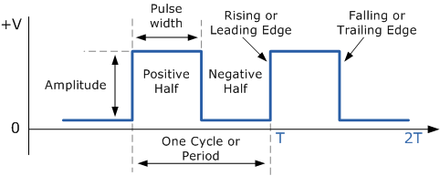
6. Trace or draw the waveform
This is a DSO inbuilt waveform. Measure the
parameters and trace the waveform.
** change the
Volts/division and time/division knob and observe the change in display.
B.
Connect Function generator output probe
with DSO input probe(ch-1 or ch-2)
All the parameters set
in Function Generators
|
Display and measure by DSO and draw any one of each of the waveforms.
|
|
Type
|
Frequency→Vpp
70Hz→.1V,
650Hz→1.2V, 1.2KHz→3.2V, 15KHz→5V
60KHz→10V
|
Parameters 1. Time period(T)
2.
Voltage peak-peak(Vpp)
3.
Frequency(F) 4.Rise time(Tr) and fall time(Tf)
|
1.Sinewave
|
||
2. Square wave
|
same
|
|
3. Triangular
wane
|
same
|
|
Sine wave (Draw at least one sine wave with
dimension)
Triangular
Wave (Draw
one triangular wave with dimension)
C. Power Supply: Operate
a power supply to generate the following voltages. Measure these DC voltages using a digital multimeter. Voltage ranges: ±5vdc, ±12vdc,
1v,2v,10v,15volts
Follow the link to know how to save DSO wave form in pen drive. (click here)


No comments:
Post a Comment