Hardware:
There are three hardware unit in this PLC. A main PLC unit, one for
water level control and other for temperature control. The main unit has
different input output elements and ports, like latch switches, push button
switches, LED indicator, anneunciator, volt meter, ammeter, relays, ADC
channels, DAC channels etc. At the back side of the main unit there are three
com ports to connect the additional units, like water level control unit,
temperature control unit, lift control unit, with the main unit.

Software:
The software used for this PLC is “PLC Trainer Ver 9.1” developed by
Kuruganti Computers Pvt. Ltd. This software has two screen or panel. One is
programming panel and the other one is display panel. When the software is
opened, the programming panel first open and from the programming panel we can
navigate to display panel by pressing F5. And we can return back to programming
panel from display panel by pressing Ctrl+L .
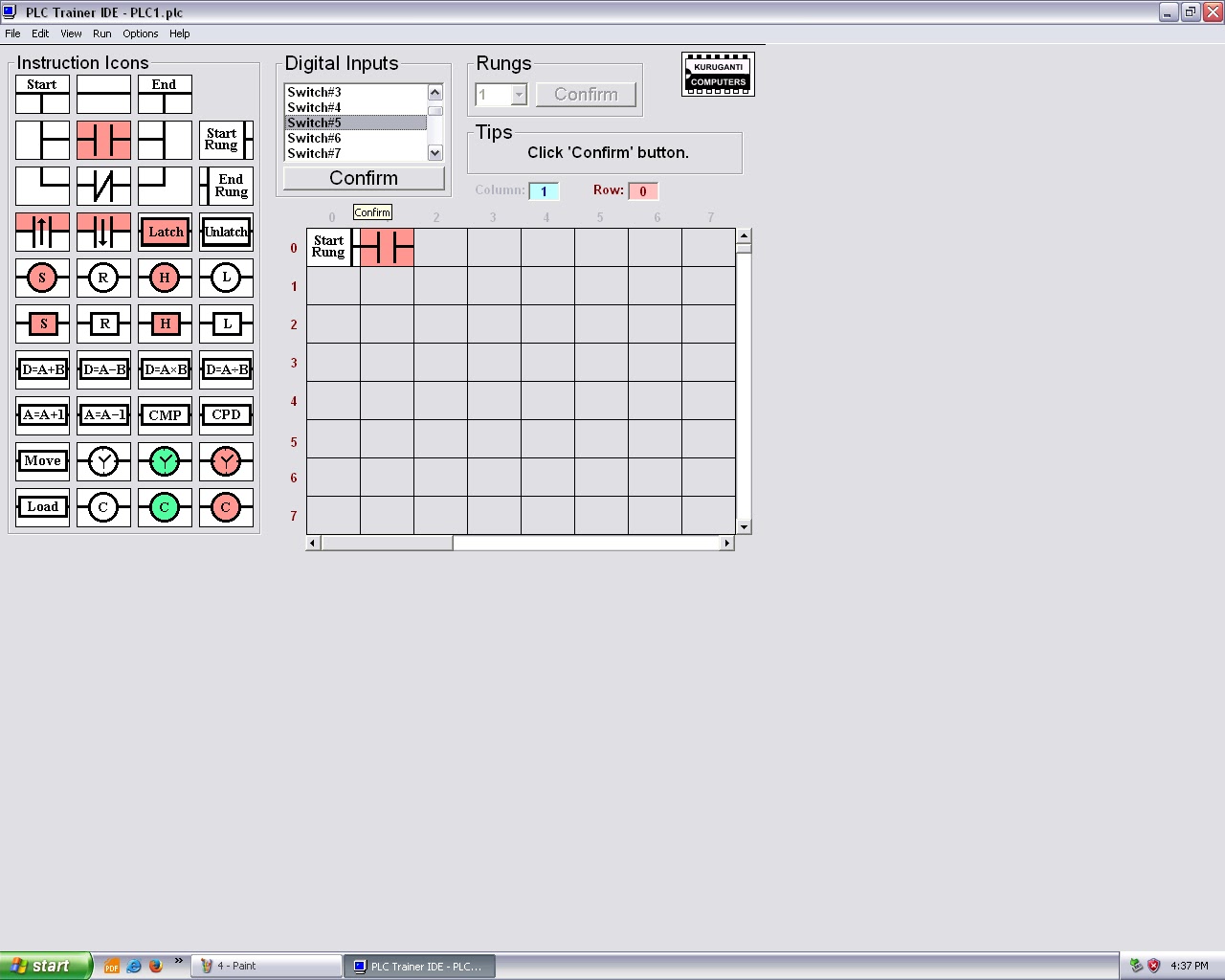
Programming Panel:
In the programming panel there are many instruction icons present and
where we can actually design our ladder diagram. The fig. shows the screen shot
of programming panel.

Each and every instruction when used in the program it should be
confirmed by clicking over the Confirm Button. Let’s know about some
instruction icons.
Rung Instructions:
Start Rung:
 This instruction signifies the beginning of a rung or line in a ladder
diagram. All rungs in a program should begin with this instruction. The Start
Rung instruction stores the rung number of a rung. The rung numbers do not
determine the the sequence of execution of rungs in a program. In the event of
an error, the rungs are addressed by their rung numbers.
This instruction signifies the beginning of a rung or line in a ladder
diagram. All rungs in a program should begin with this instruction. The Start
Rung instruction stores the rung number of a rung. The rung numbers do not
determine the the sequence of execution of rungs in a program. In the event of
an error, the rungs are addressed by their rung numbers.
End Rung:
 This
instruction signifies the end of a rung. This instruction should be used only
at the end of a rung. All rung should end with this instruction. This
instruction is the equivalent of a semicolon (;) in a high level language like
‘C'.
This
instruction signifies the end of a rung. This instruction should be used only
at the end of a rung. All rung should end with this instruction. This
instruction is the equivalent of a semicolon (;) in a high level language like
‘C'.
Input Instructions:
When High:
 This
instruction is a condition pertaining to Digital Inputs. The condition is
satisfied only when the input status of a digital input is at a logic high
state.
This
instruction is a condition pertaining to Digital Inputs. The condition is
satisfied only when the input status of a digital input is at a logic high
state.
When Low:

This
instruction is a condition pertaining to Digital Inputs. The condition is satisfied
only when the input status of a digital input is at a logic low state.
On High:

This
instruction is a condition pertaining to Digital Inputs. The condition is
satisfied only when the input status of a digital input changes from a logic
low state to a logic high state.
On Low:

This instruction is a condition pertaining to Digital
Inputs. The condition is satisfied only when the input status of a digital
input changes from a logic high state to a logic low state.
Output Instructions:
Set Output:

This
instruction is used to set a digital output to a logic high state. This is
executed conditionally, means it is executed only if the conditions preceding
it are satisfied.
Reset Output:
 This
instruction is used to set a digital output to a logic low state. This is
executed conditionally, means it is executed only if the conditions preceding
it are satisfied.
This
instruction is used to set a digital output to a logic low state. This is
executed conditionally, means it is executed only if the conditions preceding
it are satisfied.
Latch Output:
 This
instruction is similar to set output instruction. The only difference is that
there is no else statement in the equivalent. This means that once the digital
output is set, it stays set, unless another Unlatch Output instruction is used
to reset the output.
This
instruction is similar to set output instruction. The only difference is that
there is no else statement in the equivalent. This means that once the digital
output is set, it stays set, unless another Unlatch Output instruction is used
to reset the output.
Unlatch Output:
 This
instruction is similar to Reset Output instruction. The only difference is that
there is no else statement in the equivalent. This means that once the digital
output is set, it stays set, unless another Latch Output instruction is used to
set the output.
This
instruction is similar to Reset Output instruction. The only difference is that
there is no else statement in the equivalent. This means that once the digital
output is set, it stays set, unless another Latch Output instruction is used to
set the output.
When Output High:
 This
instruction is a condition pertaining to digital outputs. The condition is
satisfied only when the output status of a digital output is state at high
state.
This
instruction is a condition pertaining to digital outputs. The condition is
satisfied only when the output status of a digital output is state at high
state.
When Output Low:
 This
instruction is a condition pertaining to digital outputs. The condition is
satisfied only when the output status of a digital output is state at high
state.
This
instruction is a condition pertaining to digital outputs. The condition is
satisfied only when the output status of a digital output is state at high
state.
Flag Instructions:
Set Flag:
 This
instruction is same as the Set Output Instruction. The difference is that when
this instruction is used a flag is set instead of a digital output.
This
instruction is same as the Set Output Instruction. The difference is that when
this instruction is used a flag is set instead of a digital output.
Reset Flag:
 This
instruction is same as the Reset Output Instruction. The difference is that
when this instruction is used a flag is reset instead of a digital output.
This
instruction is same as the Reset Output Instruction. The difference is that
when this instruction is used a flag is reset instead of a digital output.
When Flag High:
 This instruction is a condition pertaining to flags. The
condition is satisfied only when the status of a flag is at a logic high state.
This instruction is a condition pertaining to flags. The
condition is satisfied only when the status of a flag is at a logic high state.
When Flag Low:
 This instruction is a condition pertaining to flags. The
condition is satisfied only when the status of a flag is at a logic low state.
This instruction is a condition pertaining to flags. The
condition is satisfied only when the status of a flag is at a logic low state.
Arithmetic Instructions:
Addition:
 This
instruction is used to add the content of two resisters.
This
instruction is used to add the content of two resisters.
Destination = Operand#1 + Operand#2
Subtraction:
 This
instruction is used to subtract the content of a resister from the content of
another resister.
This
instruction is used to subtract the content of a resister from the content of
another resister.
Destination = Operand#1 – Operand#2.
Multiplication:
 This
instruction is used to multiply the content of two resister.
This
instruction is used to multiply the content of two resister.
Destination = Operand#1 X Operand#2.
Division:
 This
instruction is used to divide the content of a resister by the content of
another resister.
This
instruction is used to divide the content of a resister by the content of
another resister.
Destination = Operand#1 / Operand#2.
Increment:
 This
instruction is used to increment the content of a resister by 1.
This
instruction is used to increment the content of a resister by 1.
Operand = operand + 1.
Decrement:
 This
instruction is used to decrement the content of a resister by 1
This
instruction is used to decrement the content of a resister by 1
Operand = Operand – 1.
Data Transfer Instructions:
Load Data:
 This
instruction is used to load a value in to a resister. When this instruction is
executed the data already stored in the destination is overwritten.
This
instruction is used to load a value in to a resister. When this instruction is
executed the data already stored in the destination is overwritten.
Destination = Value.
Move Data:
 This
instruction is used to move data from a source to a destination. When this
instruction is executed, the data already stored in the destination is
overwritten.
This
instruction is used to move data from a source to a destination. When this
instruction is executed, the data already stored in the destination is
overwritten.
Destination = Source.
Compare Instruction:
 This
instruction is a condition. The condition is satisfied only when the compare
condition is satisfied. The compare condition depends on the compare operator.
This instruction allows one to compare the content of two resisters. This
facility is essential to develop a closed loop feedback parameters like
temperature, pressure, flow etc. the list of compare operators is given below:
This
instruction is a condition. The condition is satisfied only when the compare
condition is satisfied. The compare condition depends on the compare operator.
This instruction allows one to compare the content of two resisters. This
facility is essential to develop a closed loop feedback parameters like
temperature, pressure, flow etc. the list of compare operators is given below:|
Sl no
|
Compare
Operator
|
Explanation
|
|
1
|
>
|
Greater than
|
|
2
|
> or =
|
Greater than or equal to
|
|
3
|
=
|
Equal to
|
|
4
|
Not =
|
Not equal to
|
|
5
|
< or =
|
Less than or equal to
|
|
6
|
<
|
Less than
|
Timer Instructions:
Start Timer:

This
instruction is used to start a timer. When this instruction is executed, the
timer starts running. If the timer is already running when this instruction is
executed, the timer starts again from the beginning, the previous status of the
timer is ignored. One the timer has started running, it is set after preset
time is elapsed.
Reset Timer:

This
instruction is used to reset a timer. When this instruction is executed the
timer is reset, irrespective of its previous status.
When Timer Set:

This
instruction is a condition. The condition is satisfied only when the timer is
set. This instruction is used to perform any event after a time delay.
Counter Instruction:
Increment Counter:

This
instruction is used to increment the count status of a counter. Every time this
instruction is executed, the count status of the counter increments by 1,
irrespective of the status of the counter. If the count status of the counter
is greater than or equal to the preset count value, the counter is set.
Reset Counter:

This
instruction is used to reset a counter. When this instruction is executed, the
counter is reset, irrespective of its previous state.
When Count Complete:

This
instruction is a condition. The condition is satisfied only when the counter is
set. This instruction is used to perform any event when the preset count is
reached.
Note:
To set timer value press Ctrl+t or
go to View à components
àtimer components. Then
choose the timer and set its value.
To set counter value press Ctrl+u
or go to View à
components àcounter
components. Then choose the counter and set its value.
To set resister value press Ctrl+r
or go to View à
components à
Resister Component. Then choose the resister and set its value.
Display Panel:
The display panel basically shows
the status of all input output devices, ADC values, all timer, counter and
resister values etc. the fig. shows the screen shot of display panel.

Procedure to start:

Click on the PLC Trainer Ver 9.1
shortcut over the desktop. Switch ON the main PLC unit.

Click on Continue
The programming panel will open.

Drag and drop the Start Rung over
the programming area and confirm it by clicking over confirm.
Then drag and drop other required
input output instructions and confirm each one.

The save the file. Go to Run tab
and click on compile and Run or press F5.
Then the display panel will open
where you can test your program, and see the status of input output devices.
Then go to view tab and click on ladder program or press Ctrl+l to go back to
program panel for editing the program.
No comments:
Post a Comment