Friday, 29 April 2016

Experiment 4: Study of Half wave and Full wave rectifier


Objective:-
1.      Design the circuit diagram
2.      Take the reading and draw the input & output  waveform
3.      Determine the output voltage with filter circuit across load (Rl).
Equipments required:- 

1.     Digital Multimeter
2.     CRO
3.    CDS with 5V A.C supply.
Components:-Diodes (Si-1N4007) - 4 no.s.
                          Resistor 1K-1 no.
                          Capacitor 100µF-1 no.

Thursday, 28 April 2016

Experiment 3: V-I Characteristics of Silicon Semiconductor Diode


Objective:-
1.      Design the circuit diagram
2.      Draw the characteristics curve
3.      Determine the DC forward resistance.

Equipments required:-  

1.    Voltmeter or Digital Multimeter
2.    Ammeter
3.    Bread Board
4.     Diodes ( Si- 1N4007)
5.    Resistors 1k
6.    0 - 30 V dc power supply


Forward Bias Circuit Diagram


Experiment 2: Instrument Study

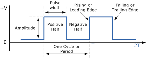
Operation of Function Generator, DSO, Power supply and Multimeter


A.    Display the internally available waveform from DSO. And measure its parameters
1.      Time period(T)
2.      Amplitude(Vm) or Vmax
3.      Voltage peak-peak(Vpp)
4.      Frequency(F)
5.      Rise time(Tr) and fall time (Tf)
6.  Trace or draw the waveform


Wednesday, 27 April 2016

Experiment 1: Study of Electronics Components

Resistors

          A resistor is a component of an electrical circuit that resists the flow of electrical current. A resistor has two terminals across which electricity must pass, and is designed to drop the voltage of the current as it flows from one terminal to the next. A resistor is primarily used to create and maintain a known safe current within an electrical component.
 

                    Physical Structure                                                                            Symbol                                                                                                                                                                     
  1. FIXED VALUE RESISTOR       (Resistor Color Code Chart)     
 
Band Color
Options
Band 1
position No
Band 2
position No

        Band 3
Multiplier Value
Band 4
Value Tolerance
Black
 0
0

×10°                                
---
Brown
1
1

×10¹
± 1%
Red
2
2

×10²
± 2%
Orange
3
3

×10³
---
Yellow
4
4

               ×10
----
Green
5
5

              ×10
± 0.5%
Blue
6
6

              ×10
± 0.25%
Violet
7
7

--
± 0.1%
Gray
8
8

--
± 0.05%
White
9
9

--
----
None
--
--

--
           ± 20%
Silver
--
--

× 0.1
           ± 10%
Gold
--
--

× 0.01
           ± 5%